Intermediate Martensitic Transformations in NiFeGa SMAs
Reginald F Hamilton, Prof. Huseyin Sehitoglu, Christos Efstathiou
A systematic experimental study is undertaken, including constant stress thermal cycling and constant temperature mechanical cycling, microstructural interrogations, and differential scanning calorimetry. We rationalize our results based on thermo-mechanical modelling approach. The results shed light on the conditions under which inter-martensitic transformations change the thermal hysteresis, the transformation temperatures, and the stress and strain levels. Inter-martensitic transformations refer to austenite converting to martensite via intermediate transitions to different martensite structures. For example, the transformation sequence in NiFeGa alloys is A⥮10M⥮14M⥮L10 or A⥮14M⥮L10 under applied compressive or tensile stress, with the L10 structure exclusively stress-induced in this class of alloys. The crystal structures are illustrated in Fig. 1.
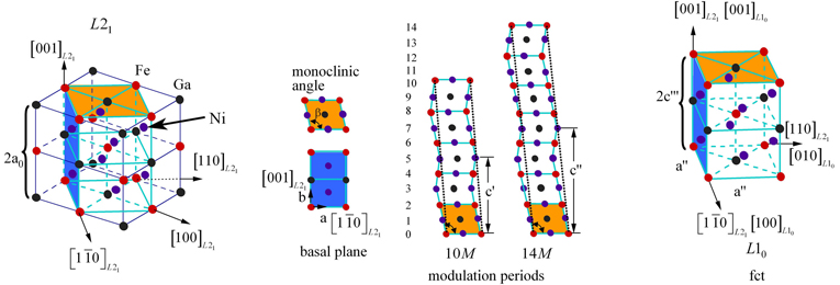
Fig 1. Schematic representations of the martensite phases in NiFeGa.
The 10M and 14M martensite are modulated structures comprised of unit cells that exhibit a monoclinic distortion defined by the angle β; a, b and c’ (c”) are the lattice parameters. The basal plane is spanned by [110]L2– and [001]L2– and the planes are stacked along the [110]L2– direction. Modulation refers to a shuffling of the basal planes along the [110]L2– direction, which is repeated every five planes to produce the 10M phase and every seven planes to produce the 14M phase. The L10 martensite exhibits a tetragonal structure without modulation. A selected area diffraction (SAD) pattern exposing the stress-free, thermally induced 10M martensite is shown in Fig. 2a. Fig. 2b shows the SAD pattern of stress induced 14M martensite retained after thermal cycling under load.
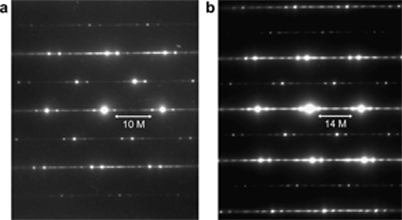
Fig 2. SAD patterns of martensite phases exhibiting (a) 10M and (b) 14M modulation.
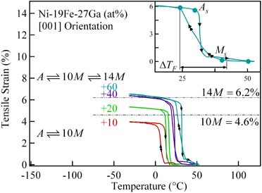
Fig 3. Tensile strain-temperature response for the transformation to the 14M structure.
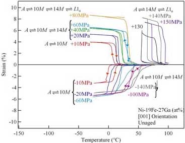
Fig 4. Tensile strain-temperature response for the transformation to the structure and compressive strain-temperature response for the transformation to 14M.
The figures above show the tensile strain-temperature response as the iso-stress increases, culminating in the formation of 14M (Fig. 3) and L10 (Fig. 4 top) martensite structures. Arrows along the curves indicate directions of cooling and heating. Remarkably, when the transformation steps are A⥮10M⥮14M, the heating and cooling segments intersect and the As temperature is lower than Ms (inset Fig. 3). A very narrow thermal hysteresis (~ 7 C) results. The responses in Fig. 4. demonstrate that the specimens fail in the range +80 to +120 MPa. At +130 MPa, the transformation and strains are completely recovered when the transformation becomes <?>. For this transformation, As > Ms and the thermal hysteresis widens considerably. In compression (Fig. 4 bottom), the heating and cooling segments intersect up to much higher stresses.
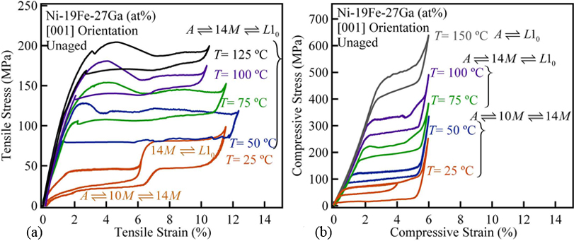
Fig. 5. Tensile (a) and compressive (b) stress-strain responses.
The figures above show the tensile (a) and compressive (b)stress-strain responses as a function of test temperature. In tension, the iinter-martensitic transformation A⥮10M⥮14M⥮L10 facilitates multiple stress plateaus; however, a single plateau is observed in compression. The tensile responses exhibit a single plateau when the transformation becomes A⥮14M⥮L10 at the higher transformation stresses observed at elevated temperatures. For both stress senses, the intermediate transition to the 14M structure facilitates a noticeable stress drop in the stress-strain curve. at the onset of the transformation. Note that the A⥮14M⥮L10 is stable up to the highest test temperatures in tension; whereas, the 14M structure is bypassed in compression. Consequently, the transformation exhibit a stark asymmetry.